 |
| Original JLH1969 Class A amp schematic |
The John Linsley-Hood 1969 Class A amplifier circuit is a classic solid state design that is carefully studied by audio designers. Even the great Nelson Pass revisited this circuit when he embarked on low wattage amplifier designs.
It has been described as one of the most tube sounding solid state amplifier designs, which is not surprising since John Linsley-Hood's references were tube amplifiers. Here's a link to the 1969 article published by Wireless World.

Since I am a DIYer at heart, I originally considered buying a pair of these circuit boards on eBay. But when I spotted a built unit for $170/shipped, I calculated that by the time I factored in the cost of a power transformer and a massive heat sinked chassis, it didn't seem wise or cost effective to go the DIY route.

The JLH 1969 Class A clone I got is branded Nobsound NS-02g but I've seen the same chassis and guts in silver or gold sporting a Krell logo!

It is very compact- a hair over 13" wide x 8.25" deep and 3" high- but it weighs 12 lbs. due to the heavy gauge chassis, massive heatsinks and power transformer. Parts quality is surprising for a $200 amplifier requiring discrete components. Input impedance is set by an Alps Blue Velvet 10k Ohm logarithmic potentiometer. There are no IC chips in this amp, just a couple pairs of transistors, a handful of resistors and capacitors + a lot of copper wire wound in the toroidal transformer. This is a true Class A design from the late 60s built at the end of the second decade of the 21st century.

When I first fired up the amplifier, I heard a buzz when the input level control was at maximum. I traced this to the IEC socket which was not grounded. Strapping the center pin (green cloth insulated wire) to ground took care of the buzz.
!!!WARNING!!!
The voltages in this circuit are potentially lethal! Proceed at your own risk!
Set Up and Adjustments
 |
| NOTE: Red probe to test point, black probe to chassis ground |
Idle Current
Out of the box, the amp sounded pleasant but I was not hearing anything magical. I was suspicious of the meager 0.5 amp AC current draw at 120V I monitored on my GenRad Variac. So removed the top cover to study the circuit and determine the purpose of the two potentiometers on each channel's PC board.
The pot towards the middle of the PC board is for idle current adjustment. Since I didn't have a manual and couldn't find one on-line, I took the cue from this video by a JLH 1969 Class A kit amp builder.👍 His circuit board looked similar enough, thus, the proper voltage must be closer to about 20V(?). I measured 26.5V and 26.2V on my unit. So I turned the pot clockwise until I got about 24 volts DC on both channels. The AC current draw was now over 1 amp and I started feeling heat emanating from the chassis.
AC Balance

The next step was to adjust AC balance. I loaded each channel's output with an 8 ohm, 20W wire wound resistor and then injected a 1 kHz sine wave at the input jacks. I adjusted the AC balance pots on both channels while observing the clipping behavior closely for best symmetry - both phases of the trace should "square off" simultaneously.
Tweaking the idle current
 |
| 137℉ @ the heatsink |
I checked the idle current once more and listened. 26V yielded almost 10 watts per channel on the bench but I felt the sound can be sweeter. At 21.5V the amp sounded excellent. But the chassis was running physically too hot. Just to be conservative, I backed off a bit and actually found the sweet spot between 22V - 24V. I also made sure there's always ample ventilation around the amp.
On the Test Bench
Top trace = signal generator
Bottom trace = amp output
 |
| 100Hz |
 |
| 1kHz |
 |
| 10kHz |
Not perfect, but nice and clean square waves from a half a century old solid-state design

Input sensitivity = .25 Vrms > ~ 6.8 watts per channel rms into an 8 ohm load with both channels driven
Tweaks
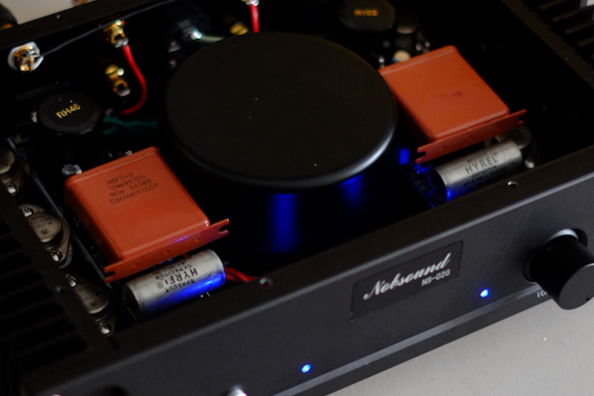
A slight glare in the upper midrange was ameliorated when I by-passed the 2.2uf input capacitors with 0.47uf Vitamin Q "Hyrel" PIOs and the 2500uf output capacitors with 10uf KBGs. Before reassembly, I also replaced the red LED pilot lights with blue LEDs. Much easier on the eyes especially in a dimly lit room.

The Nobsound clone amp spent most of its time in the system above, driving a pair of Altec 755Cs in 618 cabinets and also a pair of moderately efficient Radio Shack LX4s. I also listened to it in the main system driving the Altec 2-way. In both cases it never failed to sound sweet, fatigue-free, with a tube-like quality and depth in the midrange, maybe not the tightest bass but definition was good + airy highs.

The only time it betrayed its solid-state identity was when I spun an LP of Shostakovich Symphony No. 11 in the main system. It went into nasty clipping during orchestral peaks like a typical solid-state amp. Maybe it was asking too much from a Class A amp with a measly 7 watts rms per side to cope with the 16 ohm load presented by the Altec 2-way? However, with the same piece and on the same speaker system, my 4 watt per channel Stereo SE2A3dx with Tango NY15s went into overload with grace and composure at a similar SPL.

It is a testament to John Linsley-Hood's engineering and hearing abilities that his 50-year-old circuit is still a very capable music maker. Even if it can't replace any of the tube amplifiers in my collection, this is a much more listenable amplifier than the handful of contemporary Class D switching amps I've heard thus far.
Apostasy!
ReplyDeleteI kid, I kid! I've seen a lot of chatter on the hifi fora about this design and the latter-day versions thereof. Interesting to read you take on this amplifier. Thanks for posting it.
Hi mrh,
DeleteYour "Amp Camp Amp" might even be better? ;)
Thanks for dropping by!
JE
Do you mean replace?
Delete"when I by-passed the 2.2uf input capacitors with 0.47uf Vitamin Q "Hyrel" PIOs and the 2500uf output capacitors with 10uf KBGs."
The original caps are below the bypass caps.
DeleteHi there, I have just built a kit version of this amp. When I first powered it with my bench supply it was short circuiting (current limiting). I discovered that I did not have insulating washers on the underside of the 2n3055 mounting screws. It now plays music, but very weak sounding and each of the stereo channels is only drawing 30mA. Heat sink is stone cold.....Have I blown up the 2N3055's? Any help much appreciated.
ReplyDeleteIf you peruse this blog more extensively, you'll realize that the bulk of my experience as an audio DIYer is building tube circuits. Since I didn't build this solid-state amp from a kit, I don't feel confident giving advice regarding your issue.
DeleteHowever, I'm pretty sure you'll get good advice @ https://www.diyaudio.com/ - lots of JLH 1969 amp info can be found there.
I hope that helps!
Replace the collector load resistor of the input transistor 2n3906 with a current mirror, and you will improve distortion as the amp approaches clipping.
ReplyDeleteKevin@KAB
Thanks for the tip!
DeleteI read up on current mirrors but given my limited experience with solid state, it's still over my head. Do you have a schematic to share?
BTW, I've bought stuff from your website in the past.
I misnamed what I did. I changed the input stage using a 2 transistor cascode stage. alas, I cannot find a schematic at this time. If I come up with it, I will let you know.
ReplyDeleteThanks!
DeleteI found the circuit I used the cascode in. it was a scaled down gain stage that I used in my archival preamp. is there a way to post it here? Otherwise, I guess I could upload it to the website and link to it here.
ReplyDeleteUnfortunately this comment/messaging system doesn't have graphic capabilities.
DeleteYou can also send me another message with your email which I won't publish. I will reply to you directly so we can exchange info so you can send me the schematic as an attachment. I'll upload it as an addendum to the article above with full credit to you.
However, uploading the schematic to your website and leaving a URL link here seems like the simplest option.
Here is a link on our website for it. https://www.kabusa.com/riaa.htm
ReplyDeletein the second paragraph at the top is a link KG1.jpg. Thanks for your help. you can see the way the 2N5087 cascode is implemented. I am not sure if the resistor values need to change for the power amp or not. It will be interested if anyone tries this out. As a preamp it was quite good.
I see a basic reprint of the article on this great site https://sound-au.com/jll_hood.htm but there were some addendums as letters to the editor which included some added circuits for better oscillation stability. The version I sold for a short time back in the 90's used a current source configured using a LM317 to set the output bias. If I get a chance to shoot them, I will add them. In the end, this amp is best suited in a tri amp setup dedicated to mids and tweeters. Let something like more beefy handle the bottom.
ReplyDeleteTreasure trove link https://web.archive.org/web/20070823025637/http://www.tcaas.btinternet.co.uk/index-1.htm
ReplyDeletethis is the British site that has everything. The site is no longer active. thank God for the wayback machine.
In 1973 I got Tony Davis, technician, to design and build a 3 way Electronic Crossover amp to the Hood design. Also added was a 5W p.c. Headphone Amp, and this unit successfully drove a Kef 3way Transmission Line speaker system. The result was AWESOME, but it did generate a lot of heat at high volume.
ReplyDeleteA recent attempt to rebuild this amp has not been successful.
The system is shelved somewhere in Auckland, NZ.
Class A designs always require proper heat management for reliable operation.
DeleteThanks for sharing!